You are using an out of date browser. It may not display this or other websites correctly.
You should upgrade or use an alternative browser.
You should upgrade or use an alternative browser.
Finishing School for a Fjord 3.0 CS / 100 projects to improve a Coupe / Countdown
- Thread starter paul cain
- Start date

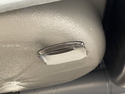
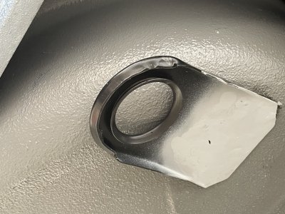
| Project 26 Reinstall the the original tiedown eyelet on to the spare tire well. This spare tire well was replaced during the body restoration. They forgot to install the original tie down. Thanks to W&N, this part is still available. |
Attachments
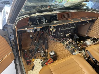
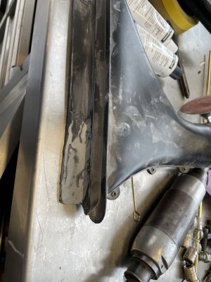
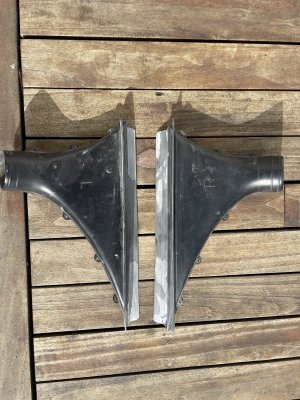
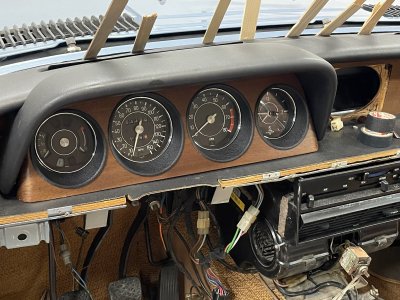
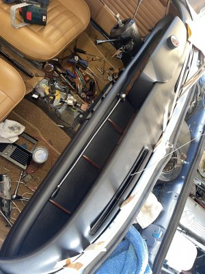
It is time to attack the interior. The refinished wood work was poorly done and will be replaced. While disassembling the instrument panel there were more discoveries of the frustrated workmanship on the entire dash. The 'installer' clearly installed the dash panels with the windscreen still in place. Which is a no-no. They forced the upper dash over the defroster vents shattering all four corners. Then they just left it floating and unattached to the four spring clips, sort of like a toupe that is three size too small. Here is the damage to the defroster vents. JB weld to the rescue. This will take about three rounds to reshape all four corners.
The three dash pads are in excellent shape having been reskinned by Just Dashes by the PO. My only complaint with Just Dashes is that the part comes back at 108% of its original size. This becomes extremely problematic when you want to reinstall your windscreen and there is no room for the weatherstripping to pocket over the steel lip. We are going to solve this issue with some more aggressive fastening of the dash to the body.
The three dash pads are in excellent shape having been reskinned by Just Dashes by the PO. My only complaint with Just Dashes is that the part comes back at 108% of its original size. This becomes extremely problematic when you want to reinstall your windscreen and there is no room for the weatherstripping to pocket over the steel lip. We are going to solve this issue with some more aggressive fastening of the dash to the body.
Attachments

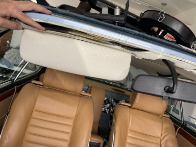
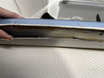
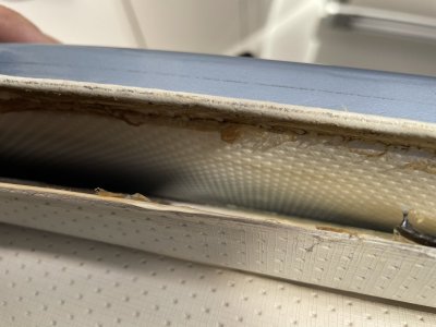
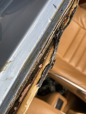
Today's discovery. We removed the front and rear glass. I knew there was a headliner fit issue on the Pass. Side at the windscreen. I had no idea how bad.
I am a firm believer in saving time, however, leaving the original headliner in place while you install the new headliner is no bueno. This is going to take some trick reworking to get that foam panel to lay flat to reattach the 'new' headliner. I am also a massive fan of the product JB Weld (image 9278). Thousands of uses, except to reattach a headliner.
Restoration work: Three steps forward. One step back. Repeat.
Attachments
Pittraider18
Active Member
This is a new kind of lazy. And I've spent years undoing hacked together Datsuns.Today's discovery. We removed the front and rear glass. I knew there was a headliner fit issue on the Pass. Side at the windscreen. I had no idea how bad.
I am a firm believer in saving time, however, leaving the original headliner in place while you install the new headliner is no bueno. This is going to take some trick reworking to get that foam panel to lay flat to reattach the 'new' headliner. I am also a massive fan of the product JB Weld (image 9278). Thousands of uses, except to reattach a headliner.
Restoration work: Three steps forward. One step back. Repeat.
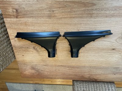
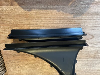
Here are the finished defroster vents at various stages of completion. It took two coats of high build primer to get them smooth again. Last photo is the vents installed with the felt faced tape to keep any noises from coming out of the dash. I use this material for all of the mounting surfaces on the entire set of wood panels as well.
Attachments

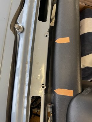
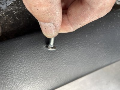
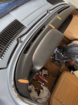
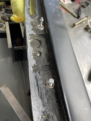
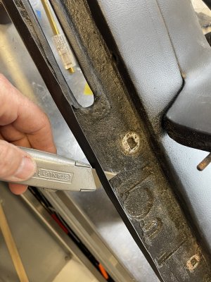
Hellbent to have the dash completely lay down on the body, I abandoned the four spring clips that the factory used. Instead I purchased 4 lag bolts about 3.5 inches long and mounted them in the same location as the original spring clips. See orange arrows. I notched the sqr hex feature that is at the base of the head of the bolt. This allows it to drop in place in the existing small sqr. holes stamped into the dash's steel inner core panel (see image 9291 center) . Then I fabricated four standoff / tubes in brass, soldering on brass washers on both ends. (The two extreme ends of this dash have two holes that are very tight in the corners and it is nearly impossible to start a nut and washer in these tight confines). The brass standoff moves this assembly bolt much lower into an accessible area on the lower edge of the dash. The two center lag bolts are accessible with the speaker removed and with the instrument cluster removed.
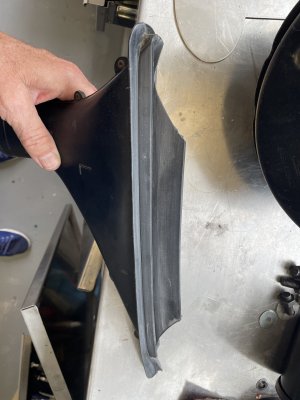
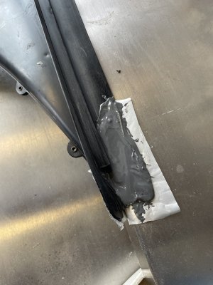
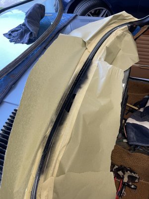
Other preparation items involved painting the entire gutter a satin black on the lower edge of the windscreen gasket. Last prep item was to clean up and shorten the forward most edge of the dash panel. JustDashes leaves a long skirt that gets in the way of the windshield gasket installation. So I cut this skirt off and epoxied that edge to give it a rounded feature and to make room for the rope that is used to pull the rubber seal over the metal lip on the body. The lower edge is very difficult with the dash being so close to this stell lip.
Last three pics are the final outcome. The four new long bolts worked great. The dash is installed. For good. As veteran members of the forum will tell you, this is a massive milestone. The remaining 50+ projects on this car are cake walk now that the dash is in place.
Attachments


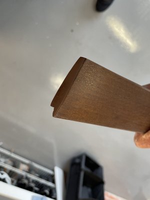
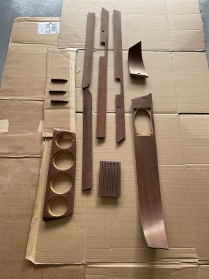
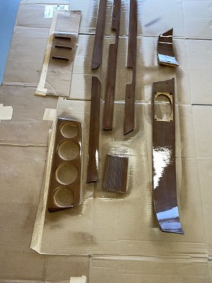
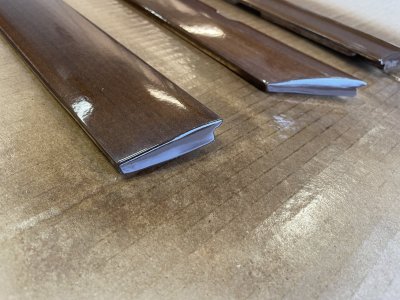
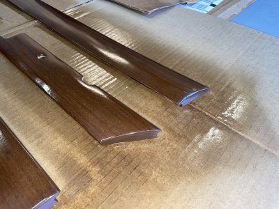
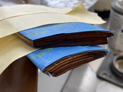
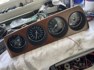
Project No. 29 replace all of the wood. I purchased a complete set of refinished wood from @TomHom. This is a very high quality kit with an excellent finish using original BMW cores on all the complex pieces. @TomHom does make a replacement speaker grille to the same OEM standard. Having a full replacement set in hand allows for a much faster swap and much less down time. the kit was close to perfect, but there a few small steps I chose to undertake before installing. First was spraying on the original brown paint on the end caps of the door and rear quarter wood. This is to hide the individual laminated edges. Then block sanding the entire set with 600 grit (dry) to apply my own preferred satin finish on all the pieces. These images show the final clearcoat wet before it dried to the satin finish. Reinstallation was straight forward with no fit issues.
Attachments

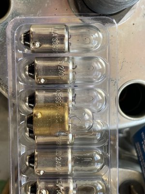
Project 30: rebuild and refresh all of the gauges. The odometer in this car was broken and there was lots of fading of the white arms. I use Gail's Speedometer Service for these straightforward projects. See: https://www.gailspeedo.com/ Mike is the owner. Super fair prices and quick turnaround times. All done via mail in. After they came back, I cleaned off all of the bulb sockets and replaced all 11 bulbs with 4 Watt. vs. the original 2 watt units. Additionally I add an extra ground circuit between the mounting plate, the gauges and the chassis ground. Se center of image 9432. Image 9436 and 9431 shows the final satin finish on the wood. The gauge cluster is back in the dash. Everything works except the green turn indicator bulb which I am still chasing down. It is starting to turn the corner in terms of difficulty. Next is to verify all chassis electrical function(s) before reinstalling the steering column.
Attachments


Good work!
The second order questions are:
1) Was the clock repaired or already working?
2) Does it keep time?
3) Will the left gauges get internal condensation on cold night drives?
As for the blinker light not working I knew once how things interrelate and fortunately even wrote it:
 e9coupe.com
The second order questions are:
1) Was the clock repaired or already working?
2) Does it keep time?
3) Will the left gauges get internal condensation on cold night drives?
As for the blinker light not working I knew once how things interrelate and fortunately even wrote it:
Turn signal and hazard clicking way too fast.
Hi all. Long time member from the BMW CS Registry. Doing some troubleshooting on my 72 3.0 CSi, driver: Symptom: Turn signal and hazard clicking way (WAY) too fast, almost a constant clicking. Turn signal actually faster. Completed: - New nickel base bulbs (7506, 5008, 3893) for...
Arde,Good work!
The second order questions are:
1) Was the clock repaired or already working?
2) Does it keep time?
3) Will the left gauges get internal condensation on cold night drives?
As for the blinker light not working I knew once how things interrelate and fortunately even wrote it:
Turn signal and hazard clicking way too fast.
Hi all. Long time member from the BMW CS Registry. Doing some troubleshooting on my 72 3.0 CSi, driver: Symptom: Turn signal and hazard clicking way (WAY) too fast, almost a constant clicking. Turn signal actually faster. Completed: - New nickel base bulbs (7506, 5008, 3893) for...
1) Yes and Yes, the clock needed the arms repainted in the flat white, the arm positions reset and the unit lubricated. This is a '74 with the first gen. Quartz movement.
2) I can report it is keeping very good time after 96 hours of being powered up.
3) I don't think the gauges will fog over with low temps, they have not done so to date. I live in a reasonably low humidity environment. (except for last week)
Thank you for the link on the hazard functionality. I will dig into it this weekend. Much appreciated.
Oh, quartz makes a world of difference...Arde,
1) Yes and Yes, the clock needed the arms repainted in the flat white, the arm positions reset and the unit lubricated. This is a '74 with the first gen. Quartz movement.
2) I can report it is keeping very good time after 96 hours of being powered up.
3) I don't think the gauges will fog over with low temps, they have not done so to date. I live in a reasonably low humidity environment. (except for last week)
Thank you for the link on the hazard functionality. I will dig into it this weekend. Much appreciated.
Mine fogged yesterday, either because I spoke or because it is Aptos...
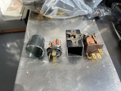
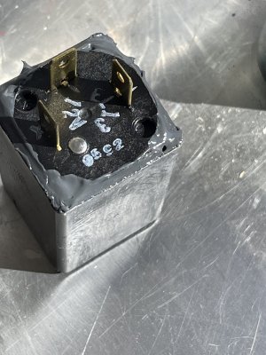
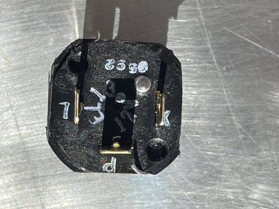
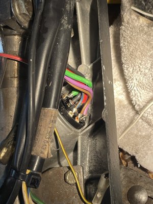
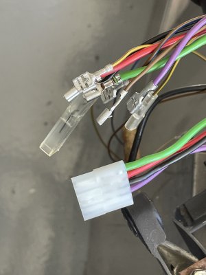
Project 31: Solve the broken lamp for the turn indicators. Symptom: turn indicators (at the four corners) work but the green indicator on the dash never comes on or blinks. Root cause: the original Hella flasher relay is highly sensitive to current flow. This does not get better with over 50 years of aging on the connectors and wiring that now have higher resistance. Solution: replace the Hella relay with an off the shelf modern fully electronic relay (EL-13) that is not sensitive to these resistance issues.
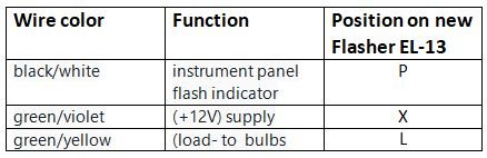
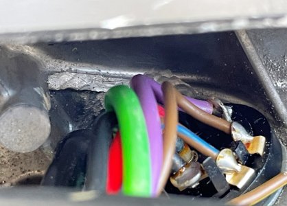
Thanks to @Dan Wood for his original contributions and wiring diagram on converting to the newer electronic flasher assembly. This quickly solved my issue with the turn indicator lamp never coming on. This is a fast and effective solution for $19 for the EL-13 flasher from Autozone. I did not want to create an adaptor harness so I just directly inserted the three pins into the new flasher after removing them from the original mating connector. To mount the flasher I gutted the original Hella enclosure and then ground down the round canister's base into a square. Dry fit it once. Then some JB weld. Looks like a stock flasher, but without the issues.
Full details are at:
e9coupe.com
The end result is a small victory, but immensely gratifying:
(this is with 4W indicator bulbs installed)
Thanks to @Dan Wood for his original contributions and wiring diagram on converting to the newer electronic flasher assembly. This quickly solved my issue with the turn indicator lamp never coming on. This is a fast and effective solution for $19 for the EL-13 flasher from Autozone. I did not want to create an adaptor harness so I just directly inserted the three pins into the new flasher after removing them from the original mating connector. To mount the flasher I gutted the original Hella enclosure and then ground down the round canister's base into a square. Dry fit it once. Then some JB weld. Looks like a stock flasher, but without the issues.
Full details are at:
yet another flasher thread...
Have been chasing the same issues everyone has, dash indicator not working. Left mostly never worked, right conked out recently. I have checked grounds, contacts, etc. in the lights. External lights always worked fine and are uniformly bright. I built the pigtail setup and added an electronic...
The end result is a small victory, but immensely gratifying:
Attachments
Last edited:
Project 32: Install a new ignition switch.
Since I purchased this car the starter when from sporadic no-starts to continuous no starts. I had already removed the steering column to do the dash installation. I flipped the column face side down on my workbench and chose to grind out the inner rib in the casting near the switch. This allows you to remove / replace the entire switch assembly without touching the entire tumbler / key assembly. Apologies I did not get photo of the ground rib prior to the installation. You can see the grinding marks in image 9464.
Next, I cut the old wire harness at about 1/2 length, leaving it installed in the car and connected to the back side of the fuse panel. By doing this I don't have to unfasten the fuse panel to swap in the new ignition harness. I then used a 4 pin connector and mated it to the new ignition switch. Now the entire column assembly is a 'drop out' with (3) easily accessible mating connectors. Senior moment: I ended up purchasing two ignition switches by mistake, if anyone is interested, image 9463 is available for $85 plus shipping.
Attachments

I’ll take the switch if still available. Will PM thanks.
Steve. It’s yours. It’ll ship in the morning.
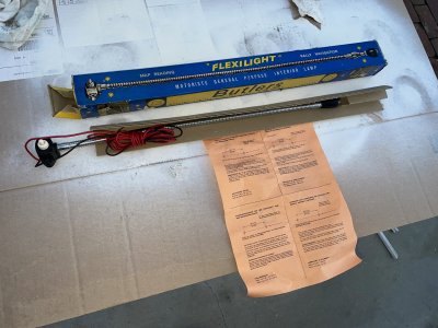
Through the generosity of @Stevehose, I had panic purchased this original Butler Map Light for the Patricia Mayer project. I ended up with two, Steve's was the better of the two (NOS and still in the box). I kept it on the 'private reserve' shelf in my garage, waiting for another worthy project. That day has arrived. It goes in tomorrow as Project 33.
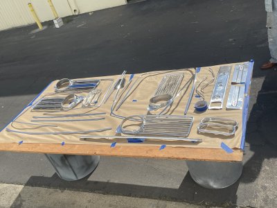
I have been breaking the hose rule of "one project at a time'' for about 4 months. I bought a Tii project and got caught up in a massive polishing and Cerikote project with
@Mike Pelly. Here are the combined parts minutes before the first coat of ceramic clear.
I have been breaking the hose rule of "one project at a time'' for about 4 months. I bought a Tii project and got caught up in a massive polishing and Cerikote project with
@Mike Pelly. Here are the combined parts minutes before the first coat of ceramic clear.
Attachments
Fritzie
Well-Known Member
Always the best part in restoration: the assembly!
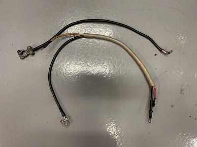
| Project 35 Replace battery cable with a mix of old jacketing and a new, correct bmw cable / clamp assembly. |
| Project 36 Replace missing bulkhead drain tubes |
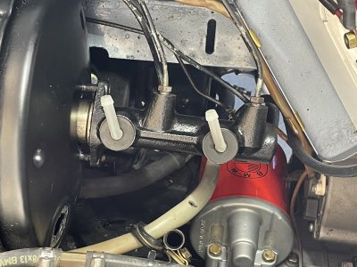
| Project 37 Rebuild brakes including new master cylinder |