final word on TPS

OZCSi

Well-Known Member
Messages
114
Reaction score
0
Gentlemen

Who knows the final word on a failing TPS solution. This part known as a throttle position sensor on a Djet is a worrying part to have issues with. Wear on the most common part of the circuit face means bucking and trailer hitching and weird behaviour at say 1500 rpm coasting .

Does anyone have a solution or option that is a known result. It still comes up in part searches but the usual result is that it is not available from bmw. Can anyone shed any precise light on this part . I have been dreading a failure and it has certainly been cleaned and preserved for years by me but the time had come.

All ideas and help is appreciated


Andrew
 

twistinglane

Well-Known Member
Site Donor
Messages
677
Reaction score
25
Location
Maryland

OZCSi

Well-Known Member
Messages
114
Reaction score
0
Many thanks. I am also a mad G wagen merc nut and will get my German friend to chase this for me now I have a direction.

Sincerely appreciated.

Andrew
 

bill

Well-Known Member
Site Donor
Messages
792
Reaction score
107
Location
stockton, nj
So you have adjusted the TPS on the throttle shaft and it's still NG? I have the bucking problem when coasting and assume it is because the TPS isn't correctly adjusted rather than a worn-out TPS.
 

OZCSi

Well-Known Member
Messages
114
Reaction score
0
Yes it appears adjusted correctly but it bucks and feels like I am towing an empty trailer. It's slight but annoying. If I had to say any other issue it if I'm cruising at 45 and bump it to 60mph it flies to 60 then I look down and feel like I have let my foot off and we are doing 55 at same throttle..

Yes I know it sounds weird, but it is happiest accelerating and unhappiest coasting..

Experts?? Come in and comment
 

OZCSi

Well-Known Member
Messages
114
Reaction score
0
Hi the number on TPS is 1 288 310 004

 
Last edited:

twistinglane

Well-Known Member
Site Donor
Messages
677
Reaction score
25
Location
Maryland
The Bosch number for the TPS is on the back. Picture attached for the 035 unit for our cars.

The number you posted is for the printed circuit board. Be interesting to know if PCB is available anywhere as I've heard they've been replaced at times
 

Attachments

  • download_20160106_082911.jpg
    download_20160106_082911.jpg
    97.5 KB · Views: 225

twistinglane

Well-Known Member
Site Donor
Messages
677
Reaction score
25
Location
Maryland
Brad Anders Rennlist site (D-jet especially for Porsche 914) contains the following. Supports your bucking problem as TPS related
I'd say replace if can...
-----------------------
http://members.rennlist.com/pbanders/djetparts.htm#troubleshoot
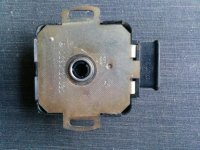
Throttle Switch
Function: Senses throttle opening (not closing), sending pulse signals to the ECU to richen the mixture for acceleration. Also senses when the throttle is closed at idling, sending a signal to the ECU to provide idle mixture compensation. Also sends a signal at wide-open-throttle, but this signal is not used by the ECU for full-load enrichment, which is handled by the Manifold Pressure Sensor.
Failure Modes:
Track Wear: Over time, the wiper track for the accelerator function will wear. Wear will be especially high at moderate to light throttle angles, corresponding to part-load cruising. Click here for a link to a 60X photo of accelerator track wear. While this TPS track is still good, the re-deposition of gold worn from the contact fingers by the wiper can be seen, and eventually will become sufficient to bridge the traces. This wear causes arcing and poor contact, resulting in the car "bucking" at a constant throttle angle. "Bucking" is a fairly common complaint and is almost always due to track wear. Check by disconnecting the harness plug to the throttle switch and driving at a constant throttle angle under part-load. If the bucking is gone, it's due to the switch. As I mentioned earlier, if you go to http://www.914world.com/ and search for user "davesprinkle", he's made a kit to replace the worn circuit board that restores your TPS to like-new condition.
Maladjustment: The throttle switch needs to be precisely aligned to ensure that the idle switch is properly actuated, and that the full extent of acceleration is covered over the range of operation. Poor idle performance and transition to full-load are affected if the switch is maladjusted. The Pelican Parts web site has a very good article on how adjust the switch, using an ohmmeter.
Notes: The car will still run even if the throttle switch is removed! It will accelerate slowly, and the idle may be poor, but it will run. Proper adjustment of the throttle switch is critical. If the idle switch does not actuate when the throttle is closed, the idle circuit in the ECU will not be activated and poor idle performance will result. Additionally, cars with ECU's that provide over-run fuel shutoff will not shut off the fuel if the idle switch isn't actuated when the throttle is closed while coasting. Proper adjustment of the throttle is also important. If the throttle cable and pedal stop are not properly adjusted so that the throttle is completely open when the throttle is fully depressed, fewer acceleration pulses will be provided to the ECU for acceleration enrichment, and you'll be restricting your full-throttle input, reducing horsepower.

I recently found out about two products that can be used on the contact tracks to extend their life. Deoxit D-5 cleans and leaves a lubricating film. It's available from CAIG Laboratories ( http://www.caig.com ). Another similar product is Stabilant 22 (VW part # ZVW 186001, Car Quest # SL-5). To use, you must open the throttle switch - be careful, there are some rubber positioning blocks that may fall out. Spray the contact track area and use a Q-tip to remove any excess.
 

OZCSi

Well-Known Member
Messages
114
Reaction score
0
Thanks so much for the advice and number clarification. I'm not keen on pulling off until I have a plan worked out....a broken piece of Bakelite in my hands is the biggest fear.

Will advise outcomes,

Thanks again
 

lloyd

Well-Known Member
Messages
444
Reaction score
94
Here is a supplemental diagnostic checklist worth reviewing: http://www.e9coupe.com/forum/showpost.php?p=24602&postcount=16

The following excerpts might prove helpful to those stalwart D-Jetters unable to locate their shop manuals.


Temperature Sensor I
Temperature Sensor I is an ambient air temperature sensor. As the ambient air temperature decreases, the density of the air increases. As a result, the ECU must inject more fuel on a cold day than on a warm day.

Temperature Sensor I is a temperature sensitive resistor known as negative temperature coefficient thermistor (NTC). This sensor has a resistance of between 400 and 500 ohms at 50 degrees F. At 100 degrees F., the resistance is between 150 to 200 ohms.

Temperature Sensor I actually has little effect on the operation on most D Jetronic equipped vehicles. This is because most of these cars have tens of thousands of miles on the engine and are running very rich due to this wear. The troubleshooting consequence of this is that disconnecting the air temperature sensor during the diagnostic procedure may have little effect on the way the engine runs, and in some cases it may actually improve the way it runs.

Temperature Sensor II
Temperature Sensor II is the coolant temperature sensor on water cooled engines. Like temperature sensor I, it is a NTC thermistor. The temperature of the engine is important because the intake manifold design of fuel injected engine does not permit the use of an air restrictive choke. Additionally, restricting the air to enrich the engine during warm up would cause inaccurate readings from the manifold pressure sensor. The warm up choke function is therefore performed by Temperature Sensor II.

When the coolant temperature is about 50 degrees F., the resistance of Temperature Sensor II is between 3000 and 4500 ohms. As the temperature increases to more that 120 degrees, F., the resistance drops to less than 1000 ohms. Thus the sensors work is done once the engine is warmed up. Also it must be continuously reminding the ECU that the engine has warmed up. If damaged, Temperature Sensor II will not continue to function partially( such as the resistance values shifting). It will completely fail, creating an open short or ground.

An open circuit in Temperature Sensor II or the wiring leading to it will cause the engine to run extremely rich once warmed up. Symptoms would be dark smoke from the tailpipe (most noticeable at idle), rough idle and poor power. Keep in mind that engine compression problems and ignition could also cause these same symptoms.

Should the sensor become shorted or the wiring harness grounded, the effects may not be noticeable at all when the engine is warmed up. The symptoms would be more like a carburetor with the choke stuck open-rough or erratic idle, stalling or hesitation when the engine is cold and progressively running better as the engine warms up.

Throttle Switch
The throttle switch tells the ECU when the throttle is closed, when the throttle is wide open and when the throttle is moving toward the open position. The switch consists of twenty-two contacts, with a set of wiping contacts that move across them as the throttle progresses from the closed position to the wide-open position.

One wiping contact is used to inform the ECU that the throttle is closed. Another makes contact only when the throttle is wide open and a third makes and breaks contact twenty times as the throttle opens. The electrical pulses created by the making and breaking of the contacts signals the ECU to open the injectors more frequently, by that enriching the mixture for acceleration. This feature behaves much like an accelerator pump on a carburetor.

Symptoms associated with a defective throttle switch include a rich(smoky)idle and hesitation. An intermittent condition at cruise-which feels like you shut off the engine and immediately turned the key back on, can also be caused by the throttle switch.

To test the throttle switch, open the throttle with the key on but the engine not running. The injectors should open exactly twenty times, evidenced by twenty evenly spaced clicks.

Pressure Sensor
The D Jetronic pressure sensor is known as a linear variable displacement transducer (LVDT).It consist of a pair of coils, one with about 150 ohms of resistance and the other with about 85 ohms of resistance. An iron core attached to a diaphragm runs through the center of these coils. As changes in manifold pressure moves the diaphragm, the iron core moves inside the coils, causing ripples in the current flowing through these coils. The ECU uses this signal to monitor the relationship between barometric pressure and manifold pressure.

The most common symptom from a defective pressure sensor is a rich running condition. Of course several other defects can cause rich running as well.

Of all the sensors used on D Jetronic, this one both the easiest and the most difficult to test. Usually a simple resistance test of the coils is enough to determine if the unit is good or bad. On the other hand, the only way to be sure is to replace it with a known good unit.

Electronic Control Unit (ECU)
The ECU receives input signals from the pressure sensor, Temp Sensor I, Temp Sensor II and the throttle switch to decide how long to leave the injectors open. It is only able to respond to air-fuel ratio request from one sensor at a time. As a result, whenever a sensor fails, the tendency will be for the ECU to send the injectors a full rich supply of fuel.

The electronic unit has no serviceable components. In the event of a failure, they replace the ECU as a unit. Failures are extremely rare and usually result in a no start.

D Jetronic that have an adjustable air fuel ratio have a detent potentiometer on the side of the ECU.This potentiometer can be used to fine tune the air-fuel ratio during a tune up.

Pin # nineteen and 25 of the ECU are connected to the fuel pump relay. When the ignition switch is turned to the on position, the ECU energizes the fuel pump to ensure that the fuel system is filled for ease of starting. If the engine is not cranked, the ECU will shut off the fuel pump after one or two seconds. If the engine is started, the fuel pump runs continuously until the engine is shut off.

In Tank Filter
Located inside the fuel tank is a screen or filter designed to protect the fuel pump from rust, dirt and debris. Although seldom the cause of a driveability problem, the in tank filter should be high on the list of items to check. In many cases these filters have been ignored, even on well maintained vehicles.”


If you are thinking seriously about replacing a TPS circuit board, this post may lead to something: http://www.e9coupe.com/forum/showpost.php?p=24898&postcount=8
 
Top