relays aren't needed to my knowledge, as you know with sardine motors, BMW ran all the power thru the switch. the original idea of relays was a way to power the motor directly (to create faster windows). i have a vague memory of somebody (perhaps M5bb - at his house) mention that the e28 motors or '74 motors didn't operate as simply as the sardine motors and needed the relay to control the up / down. i do NOT know for sure.I don’t think relays are needed but others with more experience believe they help.
You are using an out of date browser. It may not display this or other websites correctly.
You should upgrade or use an alternative browser.
You should upgrade or use an alternative browser.
A few tips on installing e28 window motors
- Thread starter jmackro
- Start date
I think there's the thinking of a voltage drop w/all that juice going through the switch.
power window wiring routes all of the current required to operate the window motors through the switches. This has a tendancy, especially after almost two decades, to burn out the switches. Carbon builds up inside the switches from arcing as the switches are opened and closed. More resistance from carbon means more heat, and slower windows. Eventually the switches may stop functioning at all.
Relays take the burden of heavy power delivery off of the relatively fragile switch, and place it on a set of contacts (in the realy) designed to handle high current. In all fairness, the switches were designed to handle the current as well, but relays are much easier to replace, and switch quickly enough that arcing is reduced, thus increasing longevity.
Baikal Bimmer
Well-Known Member
Just to clarify my concern was in regards to wiring up relays with e28 motorsrelays aren't needed to my knowledge, as you know with sardine motors, BMW ran all the power thru the switch. the original idea of relays was a way to power the motor directly (to create faster windows). i have a vague memory of somebody (perhaps M5bb - at his house) mention that the e28 motors or '74 motors didn't operate as simply as the sardine motors and needed the relay to control the up / down. i do NOT know for sure.
I didn’t add relays and they work fine, sometimes simple is best
Baikal Bimmer
Well-Known Member
Normally i would I agree, but I already have the relays in hand, and started to install them! So I would really like to use them, I just have no idea how to properly connect them
Baikal Bimmer
Well-Known Member
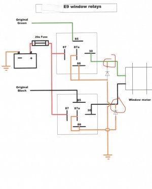
They are 5 prong relays and I have 2 relays per window, one for up the other for downso i presume you have 8 relays in hand? do you have 4 prong or 5 prong relays? i have attached the drawing i did a while back for the sardine motors.
Baikal Bimmer
Well-Known Member
Obviously some of you have wired up your e28 window motors with relays, if so how did you do it,
jmackro
Well-Known Member
See the schematic in post #4 of this thread.Obviously some of you have wired up your e28 window motors with relays, if so how did you do it,
Baikal Bimmer
Well-Known Member
It makes no mention of the PIN numbers on the relays?See the schematic in post #4 of this thread.
Baikal Bimmer
Well-Known Member
The diagram is post#47 explicitly states the PIN numbers (great for those who are electronically illiterate like me) however both Hb Chris and are confused by some of the connections which show positive and negative wires being spliced together??
jmackro
Well-Known Member
The schematic in post #47 looks OK to me. Here is a diagram that shows how the pin numbers correspond to the "guts" of a SPDT relay:The diagram is post#47 explicitly states the PIN numbers (great for those who are electronically illiterate like me) however both Hb Chris and are confused by some of the connections which show positive and negative wires being spliced together??

Keep in mind that the window switch only energizes one relay at a time. So with the top relay in the post #47 diagram energized, the green wire to the motor gets +12V and the black wire is connected to ground. And with the bottom relay energized, the black wire to the motor gets +12V and the green wire is connected to ground. With neither relay energized, both motor wires are connected to ground.
The two diodes serve as "snubbers"; they keep the relay points from burning when as relays are shut off (kind of like a capacitor across distributor points). You'll need pretty high amperage diodes for this application. You can leave the diodes out - without them the relays will only last for 25 years (with typical e9 use) instead of 50 years.
Last edited:
Baikal Bimmer
Well-Known Member
It looks like in that diagram(47) pins 87a 86 and 30 of both relays all connect together, meaning both wires of the motor would be getting positive and negative at the same time, maybe I’m not reading the diagram correctly, but if you read back on the previous page of the thread Hb Chris wondered about this tooThe schematic in post #47 looks OK to me. Here is a diagram that shows how the pin numbers correspond to the "guts" of a SPDT relay:

Keep in mind that the window switch only energizes one relay at a time. So with the top relay in the post #47 diagram energized, the green wire to the motor gets +12V and the black wire is connected to ground. And with the bottom relay energized, the black wire to the motor gets +12V and the green wire is connected to ground. With neither relay energized, both motor wires are connected to ground.
The two diodes serve as "snubbers"; they keep the relay points from burning when the relays are shut off. You'll need pretty high amperage diodes in this application. If the diodes confuse you, you can leave them out - that'll just mean that the relays last for only 25 years (with typical e9 use) instead of 50 years.
Baikal Bimmer
Well-Known Member
jmackro
Well-Known Member
Yes, pins 87a and 86 are connected to ground. Pin 30 is only connected to ground when the motor puts out a negative voltage due to back EMF. If you don't understand how that works, it's OK. As I wrote in post #72, you can leave the diodes out if they trouble you.It looks like in that diagram(47) pins 87a 86 and 30 of both relays all connect together, meaning both wires of the motor would be getting positive and negative at the same time, maybe I’m not reading the diagram correctly, but if you read back on the previous page of the thread Hb Chris wondered about this too
I'm not seeing how "both wires of the motor would be getting positive and negative at the same time".
Note that the e28 motors don't have a dedicated ground connection like the sardine can motors do. The e28 motors just have two wires: the green and the black. To get the motor to turn one way, you connect green to +12v, black to ground. And, to get it to turn the other way, you connect black to +12v, green to ground. That's what this circuit does.
Baikal Bimmer
Well-Known Member
Alright that makes some more sense.Yes, pins 87a and 86 are connected to ground. Pin 30 is only connected to ground when the motor puts out a negative voltage due to back EMF. If you don't understand how that works, it's OK. As I wrote in post #72, you can leave the diodes out if they trouble you.
I'm not seeing how "both wires of the motor would be getting positive and negative at the same time".
Note that the e28 motors don't have a dedicated ground connection like the sardine can motors do. The e28 motors just have two wires: the green and the black. To get the motor to turn one way, you connect green to +12v, black to ground. And, to get it to turn the other way, you connect black to +12v, green to ground. That's what this circuit does.
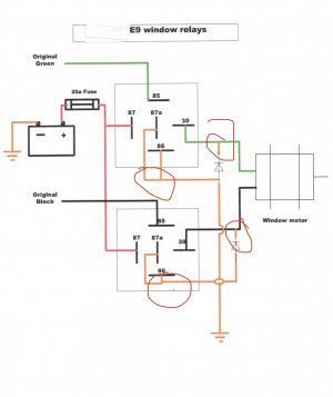
One last question, if I leave the diode out pin 30 goes straight to the motor without any contact with 87a/86
Basically the circled below disappears correct?

jmackro
Well-Known Member
One last question, if I leave the diode out pin 30 goes straight to the motor without any contact with 87a/86
Yes, that is correct - only the leads from the motors would go to pins #30 on the relays if snubber diodes aren't used.
Keep in mind that the schematic doesn't exactly say to connect pins 86 and 87a to the motor. It's just that 86, 87a and the anode end of the diode are all connected to ground, while the cathode end of the diode goes to the motor. Whether the wires that accomplish that are configured as shown in the schematic is up to you. The photos I posted in the first few posts of this thread show how I routed the wires between the relays, motors, original connector and ground.
Last edited:
Baikal Bimmer
Well-Known Member
Great I think my question is answered !Yes, that is correct - only the leads from the motors would go to pins #30 on the relays if snubber diodes aren't used.
Keep in mind that the schematic doesn't exactly say to connect pins 86 and 87a to the motor. It's just that 86, 87a and the anode end of the diode are all connected to ground, while the cathode end of the diode goes to the motor. Whether the wires that accomplish that are configured as shown in the schematic is up to you. The photos I posted in the first few posts of this thread show how I routed the wires between the relays, motors, original connector and ground.

