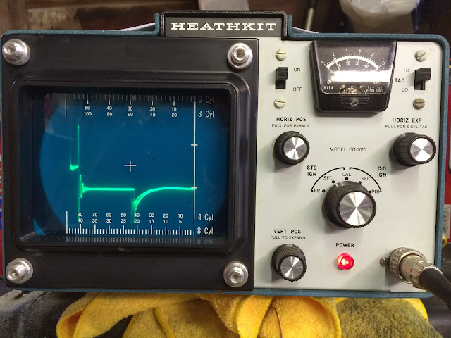
I bought a vintage Heathkit ignition scope (1972) recently and hooked it up tonight:
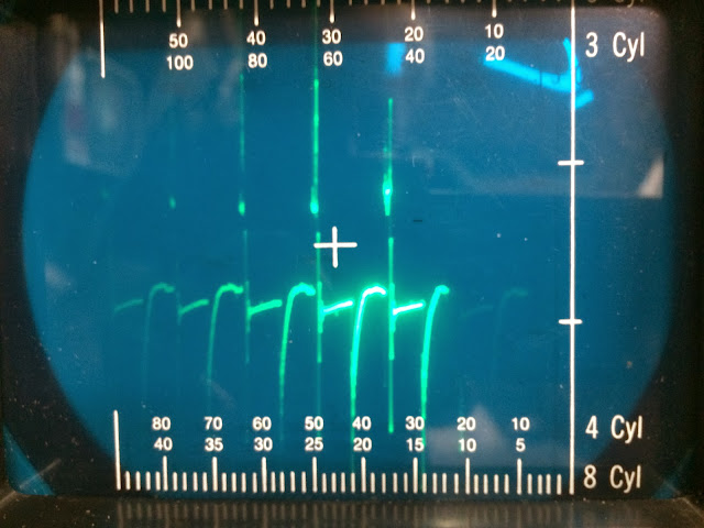
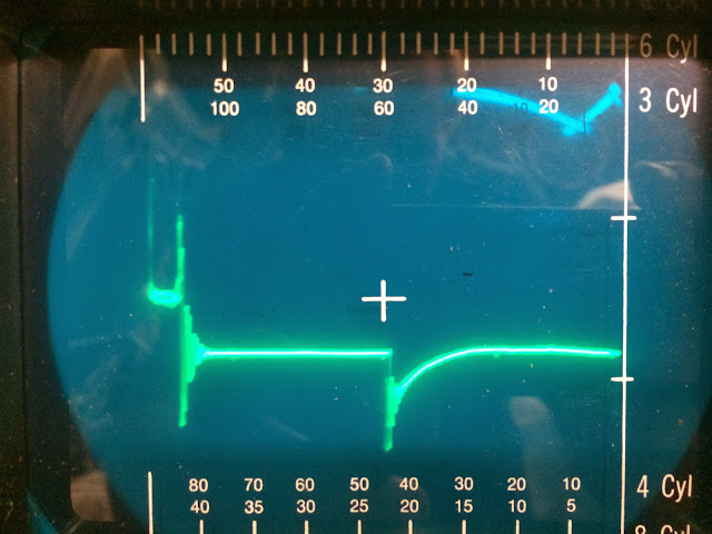
My first test run gave this wave form:
Note the upper left hand side of the trace, it starts off chaotic (this is the plug firing-it is supposed to be flat in between the spikes and not this high up according to my noob knowledge level) before going down to the first flat line (coil dissipating excess voltage). The second flat line (after the build up) is the recharging of the coil (dwell).
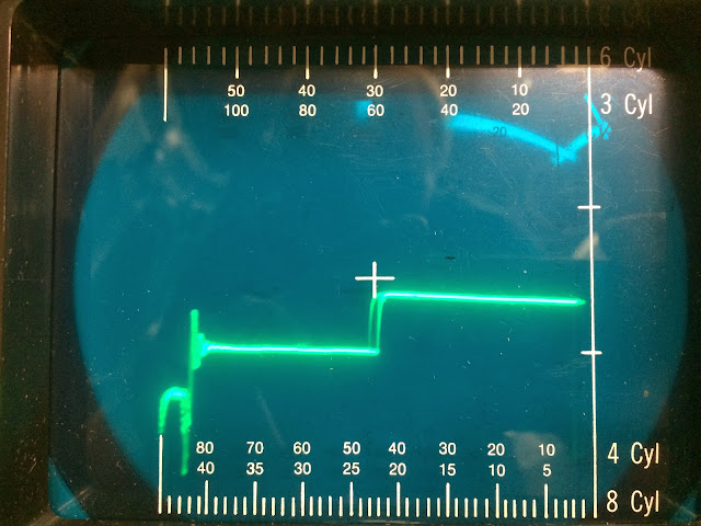
According to the stuff I've read, the plug firing stage looks like this because of high resistance in the 2nd stage, possibly from wires, cap/rotor, fuel mix, and/or plug gap. Since my other ignition components are new and I recently bumped my gap up to .030 I decided to start there and backed the gap down to .024 and got this trace:
The second trace is tighter and more uniform with less voltage spikes and the spark line is flat, lower, and longer like the books show. The dwell looks more uniform. The idle is smoother and it revs nicely although I haven't taken it out on the road yet. Pretty cool stuff.
My question is, when the owners manual says the gap should be .024 +.004 does this mean plus or minus .004 or does they mean the range of .024 - .028 and not .020 - .028?
Any other comments on the trace images from the experts that might reveal other issues? Would the trace moving back and forth (slight wobble) indicate a worn distributor?
My first test run gave this wave form:
Note the upper left hand side of the trace, it starts off chaotic (this is the plug firing-it is supposed to be flat in between the spikes and not this high up according to my noob knowledge level) before going down to the first flat line (coil dissipating excess voltage). The second flat line (after the build up) is the recharging of the coil (dwell).
According to the stuff I've read, the plug firing stage looks like this because of high resistance in the 2nd stage, possibly from wires, cap/rotor, fuel mix, and/or plug gap. Since my other ignition components are new and I recently bumped my gap up to .030 I decided to start there and backed the gap down to .024 and got this trace:
The second trace is tighter and more uniform with less voltage spikes and the spark line is flat, lower, and longer like the books show. The dwell looks more uniform. The idle is smoother and it revs nicely although I haven't taken it out on the road yet. Pretty cool stuff.
My question is, when the owners manual says the gap should be .024 +.004 does this mean plus or minus .004 or does they mean the range of .024 - .028 and not .020 - .028?
Any other comments on the trace images from the experts that might reveal other issues? Would the trace moving back and forth (slight wobble) indicate a worn distributor?