Wiring testing: temp of connectors is 60C/140F: that isn't normal is it?

eriknetherlands

Moderator
Site Donor
Messages
2,795
Reaction score
2,033
Location
Netherlands, Eindhoven area
As suggested by @Krzysztof, I proceeded to test my wiring harness under load and check for voltage drop.

Aim was to confirm if I had not damaged wiring while crawling around inside my half disassembled car over the past 5 years, and / or kinking it during removing.
As my car was running ok-isch, I'd suspected to perhaps find some gremlins or PO mods.
I also thought is was simply the best time to dig in, especially as they are now clean and on my kitchen table.

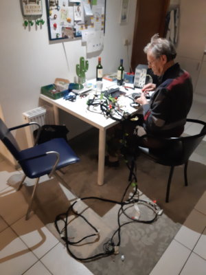
Seriously hindered by not speaking the language of electrons; i called in the help of my old man: with his university degree in physics+ 45 year career at Phillips he's better equipped then I am.

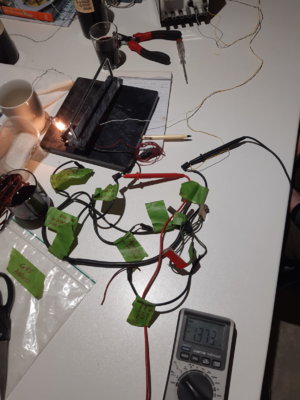
So a setup was made using a 55W headlamp, running 3,5 Amps through wire sections and check for voltage drop.
On average we see about 0.05 to 0.2 volt drop from a "connector-wire-connector" chain. However we were surprised to see up to 1,37 volts disappear in places.

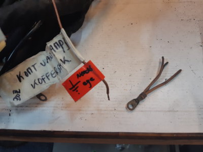
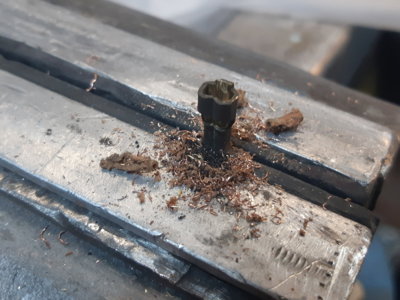
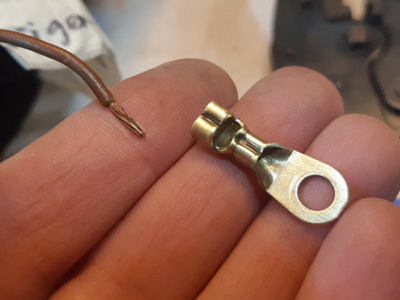
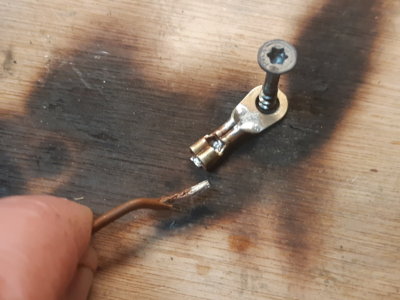
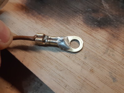
Upon further inspection we noticed that these places were all connectors where not a single, but a double wire was crimped. Some were spade connectors with double wire, some were ground-eye's with double wires. Returning parameter was that they all had crimps with two wires.
All crimps with a single wire showed values of max 0.15 volts.

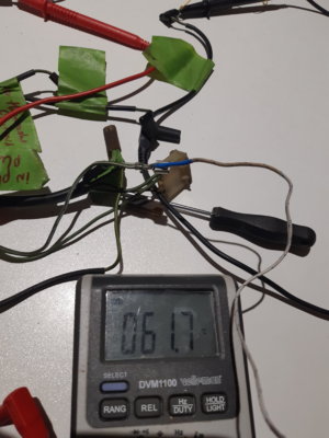
Quite consistent they ALL soak up between 0.8 and 1.37 volts. And logically they start warming up. Enclosed measurements with a thermocouple showing 61,7 celsius/140 Fahrenheit.

This can't be normal I think, is it?
I cannot imagine that an engineer would call it a proud engineering job if connectors continuously operate at 60 celsius.
Now ofcourse I run a big headlamp, so 3,5 amps through wires that are just 1,5mm2 may be a bit overkill, but the heat is localized in the crimp connection itself, not the wire.
In normal car operation most of these wires don't take this much current ; the double spade connector used for the rear lights however does takes 2x21 W + a tiny dashboard light. Is it a real problem? My car did not burn down over the past 45 years.

Is it a test setup error?
Especially the small harness on the carbs, having a few double connectors in series, was loosing the most at 1.37 volts over two double connectors in its chain.

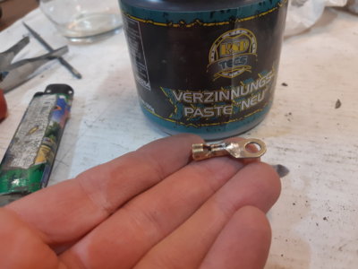
Two ground eyes also have multiple crimped wires, but they additionally also soldered: their voltage drop was significantly less at just 0.05 volts.

Questions to the group:
1. Just run as is and don't worry?
2. Solder up the double crimp connectors having a voltage drop over 0.2 volts?
3. Anything wrong with the test setup?
 

Attachments

  • 20220204_001648.jpg
    20220204_001648.jpg
    209 KB · Views: 105
  • 20220203_223221.jpg
    20220203_223221.jpg
    297.9 KB · Views: 104
  • 20220203_224049.jpg
    20220203_224049.jpg
    256.9 KB · Views: 99

Krzysztof

Well-Known Member
Site Donor
Messages
1,676
Reaction score
807
Location
Poland
Hi Erik,

As I was somehow initiator of your investigation I may start.

The load (current) of the wire should be a function of diameter. Even for ideal crimped wiring thinner wire will show bigger drop for the same current.

Another important point is how severe the circuit is and how frequent it will be in use. Good example is fog light usage versus stop light or low beam. They have different usage during "typical" year of car's operation.

So going back to your investigation. I think it is great that you've started that process as it is out of the car.

The most important circuits/wires are the one, responsible for"
- lights,
- starter,
- alternator,
as they are safety related and carrying the biggest currents.

The rest is less important and many of the wires are not carrying so big currents, thus not heating up during usage.

Dual wires crimped in a single terminal are very sensitive for poor contact as by design terminals are not designed, and is much bigger risk for worse pass resistance.

Soldering is a way to lower the resistance. It was used rarely in factory (time, cost and durability). Correctly crimped terminal is much more durable than any soldering joints as the second one is prone to cracking (solder is plastic). But if correctly crimped terminal is soak with solder, it is creating the best solution for low resistance.

So my advice for these two wire crimped terminals would be to renew them by cutting them and crimping again on the fresh copper wire if it is still above cut part. If not - in the worst case - wire would need to be changed.

I'm not sure doubling terminals would improve the situation. Not sure.

Another point for this process - very important - is to use:
- proper (high quality) terminals
- terminals for proper thickness (there are different lengths of the "wings" being folded by crimping tool
- good quality crimping tool

Oxidized, chemically treated (e.g engine bay) or overheated copper will not allow to solder it properly. Scratching is not a good idea as it is making the wire weak and prone for cracking.

Automotive temperature range is from -40 ... +85C (standard). For specific parts it can go even over 125C. So connectors should survive at least 85C but for temperatures above room temperatures (at wihich you've done the experiment) it will be higher. Simple but safe approach can be used to calculate the temperature of the teminal for higher temperatures. Just add the difference, so for 60C temperature of the terminal will be +40C higher than you've measured.
We can neglect the error caused by radiation, conduction and temperature drop while measuring with a thermocouple.

Not sure I have answered on some of doubts.
 

Arde

Well-Known Member
Site Donor $
Site Donor $$
Messages
4,751
Reaction score
1,961
Location
Cupertino, CA
Well the jump from 0.2V drop to more than 1V probably tells you it is anomalous.
The correlation with double wire crimp is interesting and suggests that when the crimp does not fully surround the wire in question the connection is compromised. Maybe it is possible to do the double wire fanout downstream of the crimp?

My concern is a positive feedback cycle where the higher temperature increases the connector's resistance and so on.
 

Ohmess

I wanna DRIVE!
Site Donor $
Messages
4,906
Reaction score
2,739
Location
Aiken, SC
Test methodology looks good. And I agree with Arde - more than 1v is problem and heat cycles will probably make the problem worse over time.

I solder everything when making electrical changes. I buy uninsulated double crimp spade connectors. I then crimp both the bare wire and insulated area just behind where I began to strip off the insulation, which doesn't help electrically, but better binds the wire to the connector. I then flow solder into the bare wire crimp, finish with heat shrink (although having just recently found a source of nicely formed insulators, I may switch over to those).

When I replace butt connections in my car, I use these: https://belmetric.com/uninsulated-butt-connector-16-14-gauge/

Bare wire goes in each end; crimp, flow solder into the opening/dent in the middle and cover in heat shrink. These can also be used for creating two into one unions.
 

Dan Wood

Well-Known Member
Site Donor
Messages
816
Reaction score
627
Location
Newnan, Georgia
If the terminals are clean without rust or dirt the voltage drop and heat should negligible. Heat is an indicator of resistance, same as the light bulb getting hot.
Volt = Amp x Resistance and Watts = Amp x Volt
I personally also like to use dielectric grease on clean connector to keep them clean.
just my 2 cents
 
Last edited:

Krzysztof

Well-Known Member
Site Donor
Messages
1,676
Reaction score
807
Location
Poland

Ohmess

I wanna DRIVE!
Site Donor $
Messages
4,906
Reaction score
2,739
Location
Aiken, SC
Let this be your guiding light:


I would (being located in EU) use TE/AMP as these were used for OE for many years. They are widely available in many flavors.

My suggestion would be to use brass, tin-plated. Much easier to solder and they are not become greenish with humidity common in cars.
Yes, I've been using Tyco Electronics parts for decades now. I persist in the view that crimping and soldering is superior to crimping. Crimping is recommended so as to make a better physical connection; and is clearly superior to attempting to create a joint by merely soldering wires together. And crimping eliminates the cold solder problem that often occurs with impatient and/or poorly trained users. Crimping is also faster when splices and/or repairs are being made by people being paid by the hour (which also contributes to the cold solder problem).

But I've been soldering for more than fifty years. And I continue to think that for anyone willing to take the time to do the best they can, crimp and solder makes sense.
 

Krzysztof

Well-Known Member
Site Donor
Messages
1,676
Reaction score
807
Location
Poland
I agree that crimping and soldering is the best, well known method but I have seen many only soldered wires and they were fine over years.

It is just my engineering-focused brain, reminding me it is not the way it should be done :D . What a habit!
 

eriknetherlands

Moderator
Site Donor
Messages
2,795
Reaction score
2,033
Location
Netherlands, Eindhoven area
Thanks to member @Hans woonboot, who kindly donoated some parts, a few connections are now improved:
Old wire with ground eye missing and spare from Hans.

The donor is a bit oversized, but that will be remedied with solder.
Pics:
Drilled out old wires
Cleaned up with glass bead blast and sanding.
Soaked in etching primer to get rid of old oxidation & tin the surface.
Soldered!
 

Attachments

  • 20220207_223233.jpg
    20220207_223233.jpg
    189.5 KB · Views: 79
  • 20220207_223433.jpg
    20220207_223433.jpg
    300 KB · Views: 87
  • 20220207_223937.jpg
    20220207_223937.jpg
    186.2 KB · Views: 80
  • 20220207_224924.jpg
    20220207_224924.jpg
    205.9 KB · Views: 77
  • 20220207_225006.jpg
    20220207_225006.jpg
    234.6 KB · Views: 80
  • 20220207_230232.jpg
    20220207_230232.jpg
    256.6 KB · Views: 90

Ohmess

I wanna DRIVE!
Site Donor $
Messages
4,906
Reaction score
2,739
Location
Aiken, SC
Very nice clean up. I have historically used naval jelly for cleaning up electrical connectors, but whatever it is that they now sell as naval jelly does work as well as the dangerous phosphoric acid of old. Perhaps I'll change to etching primer.

I much prefer to learn to carefully use something dangerous that will do the job, as opposed to patiently waiting for something that will not, in my lifetime, get the job done. I must be in the minority in this, because most of the retail stores in the US are chock full of inadequate tools, solvents, and cleaners.
 

Krzysztof

Well-Known Member
Site Donor
Messages
1,676
Reaction score
807
Location
Poland
@eriknetherlands

It should work even if the thickness ground eye was designed for is far from the one wire you've used. There any still many of these available even from BMW for not a big money (if someone needs few only).

I was using warm/hot dissolved citric acid (easy to buy in grocery store). It is eating up most of oxidation without sanding. later on scotch-brite-like to polish. Just not to keep it too long as the part will become dark and require more polishing.

I would consider to protect renewed terminal against new oxidation. Electrical contact spray (the one with protective oil/grease) should do the job, keeping shiny and - what is more important - well contacting junction.
 

tferrer

Well-Known Member
Site Donor
Messages
2,153
Reaction score
2,336
Location
San Francisco, CA
I was turned on to Deoxit by someone here. Works really well.


This
for connections after cleaned which I've begun to use on grounds. Preliminary test implies it works really well. You only need the teeniest amount. It gets everywhere so apply with a small swab or toothpick.

MG Chemicals - 8481-1 Premium Carbon Conductive Grease, 3 fl. oz, Black https://www.amazon.com/dp/B00NB14C2...t_i_ZN08FH1YKACWR8DQ9JEN?_encoding=UTF8&psc=1
 

Ohmess

I wanna DRIVE!
Site Donor $
Messages
4,906
Reaction score
2,739
Location
Aiken, SC
I was turned on to Deoxit by someone here. Works really well.


This
for connections after cleaned which I've begun to use on grounds. Preliminary test implies it works really well. You only need the teeniest amount. It gets everywhere so apply with a small swab or toothpick.

MG Chemicals - 8481-1 Premium Carbon Conductive Grease, 3 fl. oz, Black https://www.amazon.com/dp/B00NB14C2...t_i_ZN08FH1YKACWR8DQ9JEN?_encoding=UTF8&psc=1
Yes. I used to use that stuff on video board repairs. Its excellent for sensitive electronics. It is available in small bottles with a brush, and a five ounce bottle lasts years.
 
Last edited:

Krzysztof

Well-Known Member
Site Donor
Messages
1,676
Reaction score
807
Location
Poland
Thanks.

There are some similar products also in EU. Hard to tell which is the best.

I was using quite cheap one and worked well I think.
 
Top