Electric window relay upgrade

Stevehose

Well-Known Member
Site Donor $$
Messages
13,003
Reaction score
5,679
Location
Sarasota, FL
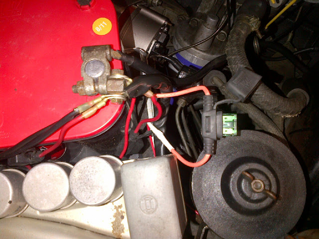
Finished today a week-long project installing relays on each of the electric windows. I followed the postings of Jmackro and Jhjacobs. I hooked up a 12 gauge wire (30 amp fused - orange wire in the pic) to the battery:

IMG-20111231-00174.jpg


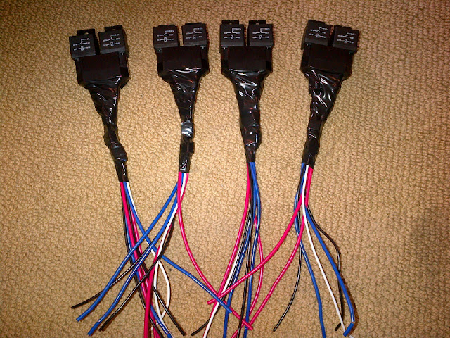
I had bought dual relay sockets and relays off eBay, removed the open 87a wire, soldered in the diodes per John's diagram, and taped them up:

WindowRelay.gif


IMG-20111224-00150.jpg


IMG-20111224-00153.jpg


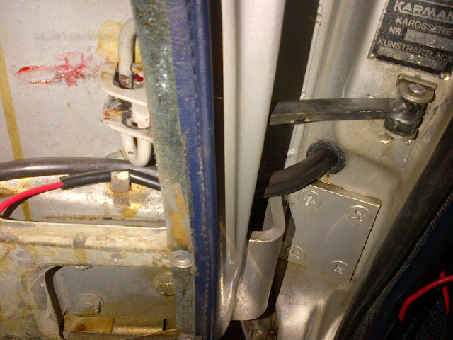
Then I wired the car - I ran the wire from the battery through the firewall off to the driver's side where I spliced into it for the driver's door and ran a line behind the a/c evaporator to the passenger door, each was wired through their own tubes past the hinges since I couldn't fit this wire through the existing tube and I didn't feel like devising a new one for all the wires:

IMG-20111225-00155.jpg


IMG-20111225-00158.jpg


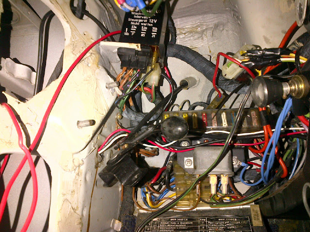
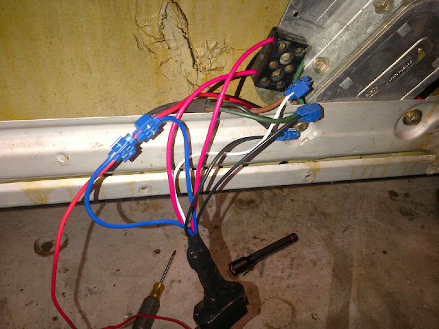
Then I wired in the relays - the front motors have 3 wires, the middle brown one is ground so I took the wires at the junction box from the switches and spliced them to the relay up and down inputs (black wires), spliced the brown ground wire to the white ground of the relays and ran a separate wire (red) from the old middle junction box wire also to ground, and installed the battery lead to the relay (blue wires) and the power out wires to the motors (red wires).

IMG-20111225-00160.jpg


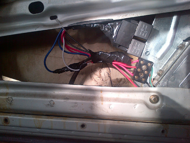
And drilled a hole for mounting and zip tied and taped it all together:

IMG-20111230-00168.jpg


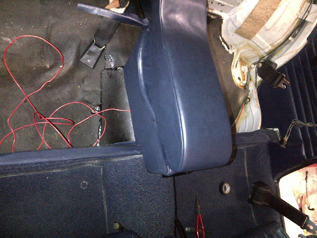
Then I ran the wire from the fuse box area along the driver's side under the carpet to the back seat area, this is the shortest distance to access the back windows, I ran the wire past the driver's rear window then across to the passenger rear window and terminated it there. I spliced into this wire for the driver's side rear window.

IMG-20111230-00170.jpg


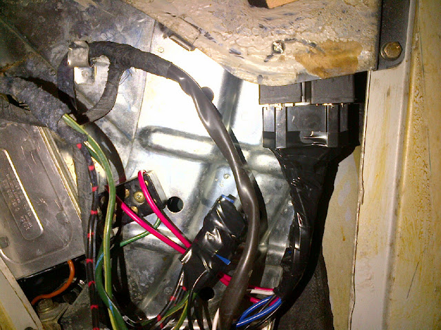
And drilled a hole and installed the rear motor relays:

IMG-20111231-00172.jpg


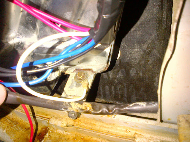
And since the rears don't have a middle junction box ground I grounded them at the bottom window mount bolt (white wire):

IMG-20111231-00173.jpg


The result is definitvely faster windows, even though I had previously rebuilt and regreased mine and were already pretty quick, with the extra voltage they are faster - and better still the amperage is no longer running through all the old wires and switches. This is an excellent mod which, like the low beam head light circuit relay mod, adds safety and corrects a design flaw in these cars. Thanks to the guys that posted this previously and I hope this details from start to finish enough of the process so those with average mechanical skills like myself can undertake this upgrade.
 
Last edited:

deQuincey

Quousque tandem...?
Site Donor
Messages
8,418
Reaction score
2,431
Location
BIO - 43°15'46.5"N 2°56'03.7"W
great steve,

i will do this !, but I am afraid i will need to ask you some questions, as I didnt undestood all the process

in my case only rear windows are affected

first question: which type of relays ? data ?

thanks
 

Nicad

Well-Known Member
Site Donor
Messages
3,517
Reaction score
542
Location
Toronto
Gonna pour through this info when I get some clear time. Good work Steve. Keep on improving.
 

Stevehose

Well-Known Member
Site Donor $$
Messages
13,003
Reaction score
5,679
Location
Sarasota, FL
I bought these cheapo ones, but any standard 4 or 5 pin 12v 30 amp relay will work:

http://www.ebay.com/itm/200690347825?ssPageName=STRK:MEWNX:IT&_trksid=p3984.m1439.l2649

These are 5 pin, which means pin 87a is an open circuit with the power source, I removed this pin which is the middle one since it is not needed for this purpose. Same style relay as used for our high beams and horn. The convenient thing is to get them with the dual socket so they can be installed as one unit. Pins 85 and 86 are used for the switch input and ground - these sockets came wired together with a common white ground wire which eliminates a duplicate ground wire. 12v from battery is wired to pin 30 and pin 87 goes to the motor. The pin socket/female connector can be removed with their wires by inserting a small pointed object into the socket and bending back the small tab that holds it in. I used a straight seal puller/pick for this.


first question: which type of relays ? data ?

thanks
 

jmackro

Well-Known Member
Messages
2,463
Reaction score
728
Location
San Juan Capistrano, Ca.
Steve:

Yup, that's pretty much the way that I did it too. Like you, I installed "anti-flyback" diodes, which should extend the life of the relays.

The only other thing I did was to run a ground wire directly from the motor, through the wiring tube that spans the door-body, and secure it directly to the body. That way, the hinge pins aren't carrying the ground current.
 

Stevehose

Well-Known Member
Site Donor $$
Messages
13,003
Reaction score
5,679
Location
Sarasota, FL
I thought about doing that, but doesn't ground current also go through the door latches in addition to the hinges? Seems like that would suffice. Anyway, my motors are enjoying the extra juice!

The only other thing I did was to run a ground wire directly from the motor, through the wiring tube that spans the door-body, and secure it directly to the body. That way, the hinge pins aren't carrying the ground current.
 

PaulinPa

Well-Known Member
Messages
528
Reaction score
14
Location
Bainbridge,Pa.
After gathering all the necessary relays and diodes and wire I thought I would give this window upgrade a try.However I didn't get too far.In this picture: https://lh5.googleusercontent.com/-P...1224-00150.jpg
where does the short red wire with the diode attached go?I see the end with the gold clip must go back in the relay body but the short length looks like it's just... there? Any help appreciated!
 

Stevehose

Well-Known Member
Site Donor $$
Messages
13,003
Reaction score
5,679
Location
Sarasota, FL
They go to ground, which in my setup pictured is the white wire, shared between the 2 relays. The diodes are wired together with the white wire. Note the diodes are directional so make sure they're wired correctly.


After gathering all the necessary relays and diodes and wire I thought I would give this window upgrade a try.However I didn't get too far.In this picture: https://lh5.googleusercontent.com/-P...1224-00150.jpg
where does the short red wire with the diode attached go?I see the end with the gold clip must go back in the relay body but the short length looks like it's just... there? Any help appreciated!
 
Last edited:

autowerks

Well-Known Member
Site Donor
Messages
561
Reaction score
82
Location
Dallas, Texas
Thanks Tony, I hope it is all well with you and the family.Yes I got the Vertical window trim fixed, koopman was nice enough to send me one.
 

SME9

Active Member
Messages
53
Reaction score
18
Location
Lurking Down Under....
Time to bump this post up the chain again.

I'm wanting to do the window relay upgrade on my 74 CS, but I've had zero luck in getting ANY window movement. My motors appear to be a different version (Bosch product, same as Porsche 911 window motors), with a black plastic casing on the outside, and four pins on the bottom - two of which are used. My owner's manual electrical diagram shows a different wiring setup (three wires, black, brown and green), but my car appears to have factory wiring using only two wires (blue and black)...

I connected up the twin relay, and when switching, I'm getting 12v to the pins on the motor but zero movement. When disconnected and wired in factory form, they go up and down.

I'm pretty slow when it comes to electrics, and I'm definitely scratching my head at this one...

Anybody have any pointers?
 

HB Chris

Well-Known Member
Site Donor $$
Messages
19,418
Reaction score
8,759
Location
Huntington Beach, CA
Mid 73 thru 74 coupes have later motors like the Bosch e28 motors with two wires vs the early sardine can motors. I personally don’t think there is too much of a difference with these. Most if not all write ups focus on the sardine cans.
 

jmackro

Well-Known Member
Messages
2,463
Reaction score
728
Location
San Juan Capistrano, Ca.
first question: which type of relays ? data ?

This question - asked by deQuincey back in 2012 - may bear on problem SME9 is currently having.

The type of relay is dependent on the type of motor you are using:

- The wiring diagram that Stevehose posted at the beginning of this thread uses SPST relays, which are applicable to the original, "sardine can" motors used in pre '74 e9's. As Steve's wiring diagram shows, those motors have three wires: black, green, and brown (which is ground). Hook power to the black and they turn in one direction, to the brown and it turns in the other.

- The wiring diagram that I posted in the thread at https://www.e9coupe.com/forum/threads/a-few-tips-on-installing-e28-window-motors.27320/ uses SPDT relays, which are applicable to the newer, e28 rear motors. These motors have two wires (black and blue): connect one to +12 and the other to ground and the motor turns in one direction, reverse the polarity and it turns in the other.

Note: The abbreviations "SPST" and "SPDT" stand for "single pole, single throw" and "single pole, double throw". If all you can find are double pole relays (e.g., "DPST" or "DPDT"), they'll work OK too. The second pole on each relay simply won't be used.
 
Last edited:

deQuincey

Quousque tandem...?
Site Donor
Messages
8,418
Reaction score
2,431
Location
BIO - 43°15'46.5"N 2°56'03.7"W
adding this info if you find anything worthy
i stand on the shoulders of others as @jmackro and @Stevehose

 
Top